
2006-12-19
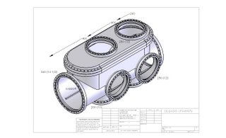
Updated drawing for the chamber
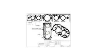
This is a drawing where the specs for the flanges are included. The vertical distance main axis-support plane is 152.1 mm. The dimensions have been checked with the real chamber. Sorry about the jpg resolution, I can send you a well resolved eDrawings file if you wish.

2006-12-06
2006-12-05
2006-12-04
10-7 mbar!
The chamber has finally been pumped down to 10-7mbar by the help of the vacuum group in Hamburg. Vielen Dank, Maike Röhling, Lutz Bittner, Nicole von Bargen und Björn Timmannn!


2006-11-17
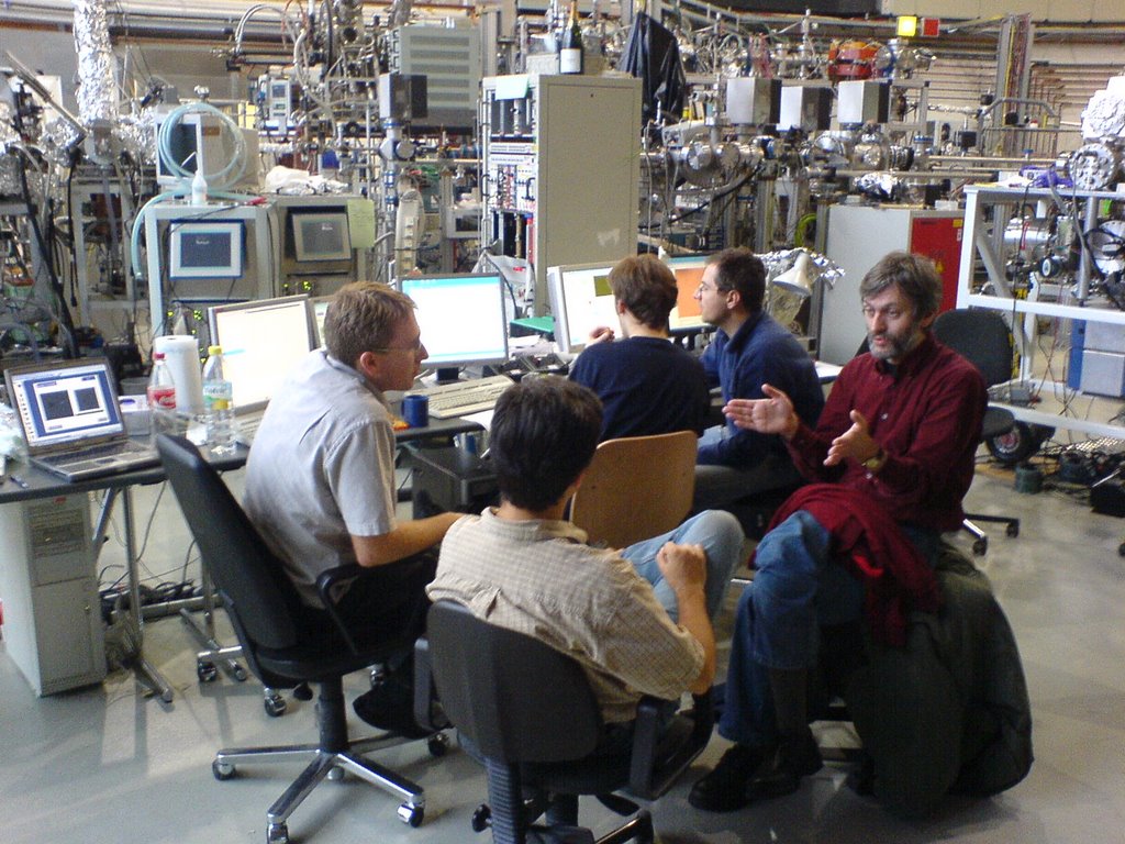
First beamtime shift successful
This night, plenty of images were taken of fixed samples. The shorter (13nm) wavelength, as compared to last beamtime in February, makes life a lot easier for imaging.

2006-11-13
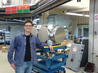
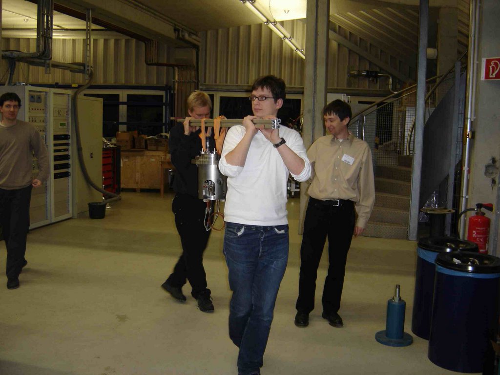
Chamber on the stand at Flash!
Today we mounted the Uppsala chamber on the Hasylab stand. Now we are waiting for the flanges, which should be delivered later this week. When they are here, we can start the mounting of the pumps and hope for good vacuum.
The roadmap for the use of the chamber will be clearer in a day or two. The first use of the chamber will be the testing of the Livermore inset with the particle injection system, and a YAG laser. This testing will possibly be done in January, in time before the February beamtime.
The roadmap for the use of the chamber will be clearer in a day or two. The first use of the chamber will be the testing of the Livermore inset with the particle injection system, and a YAG laser. This testing will possibly be done in January, in time before the February beamtime.

2006-11-08
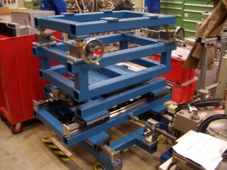
Chamber stand!
This is the chamber stand that the group of Ulrich Hahn at Hasylab have built for us. Now it is waiting for the chamber!

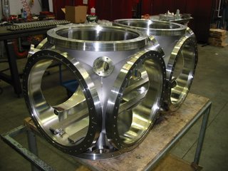
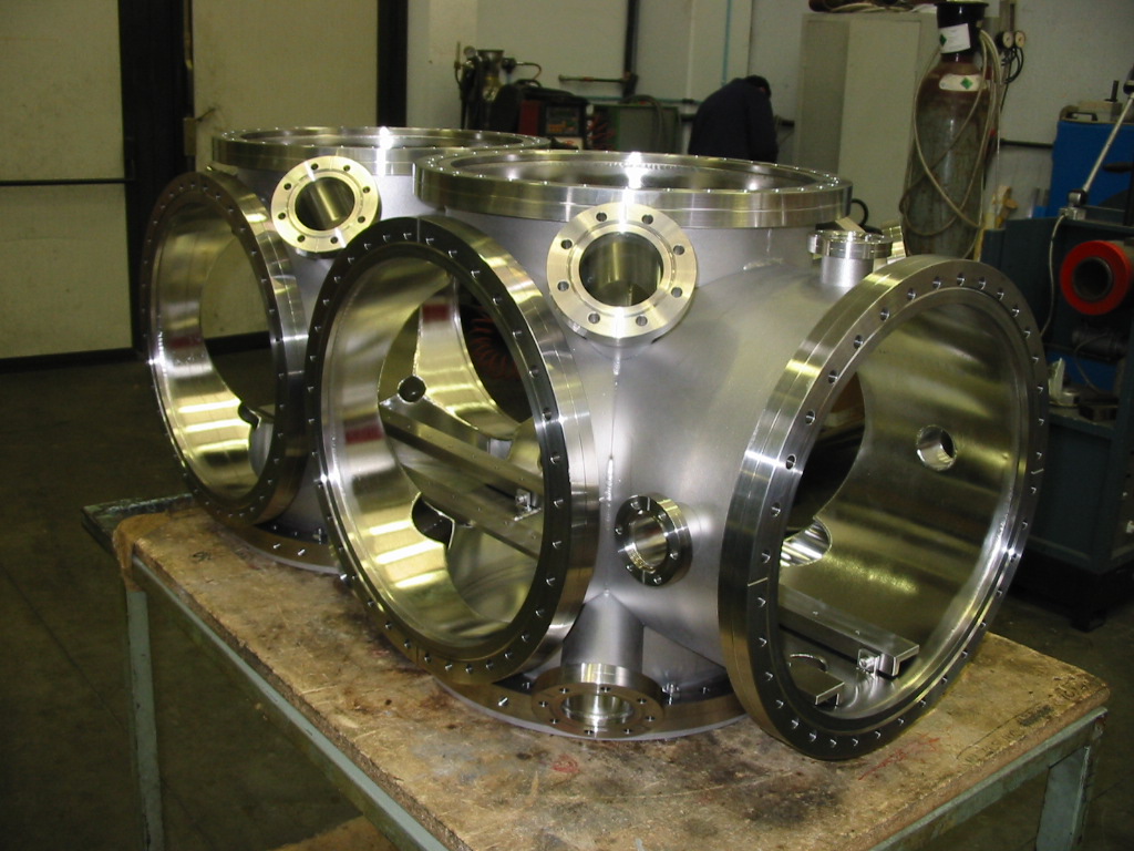
Chamber!
Here are photos taken today in Parma. The chamber will arrive in Hamburg on Friday. The viewports and removable supports (previously denoted rails) look OK!
The plan is to use the chamber after the November Flash beamtime (ending on the 24th of November) for further testing of the Imaging experiment, e.g. the new MS-TOF.

The plan is to use the chamber after the November Flash beamtime (ending on the 24th of November) for further testing of the Imaging experiment, e.g. the new MS-TOF.

2006-10-05
Discussion for Thursday the 9th with Allectra

I will go to Parma tomorrow (Wednesday) to see the chamber, and meet with Mario Peli, the Allectra engineer. And eat some prosciutto. :)
We intend to use the chamber in November for test purposes. The particle injection system will be mounted from the left, a Nd:YAG laser comes from the front and a beam dump/ power meter will be mounted on the rear side.
Before, we discussed the option to have off-centre CF 360-35 nipple adapters.
The IAR, Interaction Region, is given by the distance to the 250 top flange (presently given by the Berlin chamber).
However, it is much more convenient to have the interaction region at the centre. That would require a CF 360-250 well adapter, with a depth of 156mm. The problem to solve is that there is space for nitrogen pipes (Swagelok connections on the top 250 flange, pointing to the right). The special geometry of this well adapter is the first topic to discuss in Parma.
List of topics:
1) Well adapter (see above).
2) Geometry of the viewports, so that they do not collide with the 360 flanges.
3) 360-35 nipple adapters.
4) Support for the breadboard in the chamber (previously misleadingly denoted rails).
5) Date for chamber delivery to Flash.
6) Lugs, the interface chamber-stand.
2006-07-11
Drawings sent to Allectra

Here is the drawing file of the Zeppelin chamber that I have sent to Allectra. Production time is 10 weeks, so we can expect to have the chamber delivered at the end of September.
On the drawing at least 1 source of potential confusion can be seen:
1) According to Henry Chapman, the submicron optics will be placed 100mm off-axis, 250mm downstream the chamber. So the submicron plane would be 220+250=470mm from the front flange. I have instead put it slightly off: at 445mm. It is a compromise, with a submicron plane at 400, we could use the submicron optics pointing towards the interaction region IAR670. Now the viewports can be used for both possible geometries.
In an earlier version of this blogpost, a second potential source of confusion was mentioned, but since then the interaction regions IARs were set to be centered with the CF360 flanges, simply to minimize confusion.
The definite geometry of the rails will be postponed until I have interacted more with the people constructing the parts to mount there.
I can send you eDrawings, DXF, DWG, etc. files on the chamber if you want to have a closer look. Last minute changes are welcome until Thursday the 13 of July.
2006-06-08
Movie
I have started with videoclip recording on the chamber. Anyone interested? Can be used for ppt presentations etc. Formats: avi, bmp or tga. (OK for e.g. Quicktime, Windows Media Player, etc.).
Pumping, cont.
Why not using a cryopump, e.g.: shi?
The initial costs are comparable to a turbopump, the maintainance costs are significantly lower.
The main reason why cryopumps are not standard for experiment chambers is that they vibrate (remember the 2Hz tf-tf-tf from the mono beamline at the Flash). I will get specs on the vibrations.
Back to turbos, an issue is to prevent the rotating alu blades from, e.g. falling screws.
-The standard solution is a net. The drawback is 25% reduced pumping efficiency.
-If we choose to mount the turbo to the side or upwards, we will not need any net. But the chamber will be less bottom-heavy.
2006-05-24
pumping
a few parameters to be considered for pumping:
1x10^-8 mbar vacuum.
the load of the rare gas clusters is 0.1mbar x l/s, requiring a 1000l/s turbomolecular pump.
the inner area of the chamber is 2m^2.
the volume of the chamber is 0.16m^3.
the area of the llnl experiment is 3m^2.
for the previous experiment we had a 1000l/s pfeiffer corrosiveturbo vacuum pump, which needs a backing pressure of 10^-2 mbar. a scroll pump is good for that.
comments from christoph bostedt, berlin:
S=R*A/p
and R=8*10exp-9 mbar/(sec*cm^2) (outgassing stainless steel after one hour pumping), A ca 2*10exp4 cm^2, p=10exp-8mbar
i.e. 16000 l/sec needed sucking capability. which would be gigantic!
to save the day: R can be reduced by electropolishing, and we can work at worse vacuum than 1e-8mbar, so we can reduce S by an order of magnitude.
so we would need app. 2 1000l/s pumps for the chamber, and 1 1000l/s pump for the clusters.
2006-05-23
positioning of the chamber
thk: csr
yesterday, thk representatives were here to present their product. now i am waiting for them to present a full 6dof (six degrees of freedom: xyz, and three angles) positioning solution, possibly based on the csr standard. the motors for the positioning of the linear motion (lm) blocks would be provided by omron.
the previously used positioning setup of the moller group was also based on thk, with
phytron motors. phytron is the standard at desy.
the previous thk:csr setup was normal precision grade, i.e. stable and repeatable position on a 10um scale. thk also provides super precision and ultra precision grade, with 7 and 5um precision, respectively.
with the submicron optics, we need submicron stability over 10 minutes (a low-fluence run). over 12 hours, we need 10um stability.

2006-05-12
chamber on minitec frame
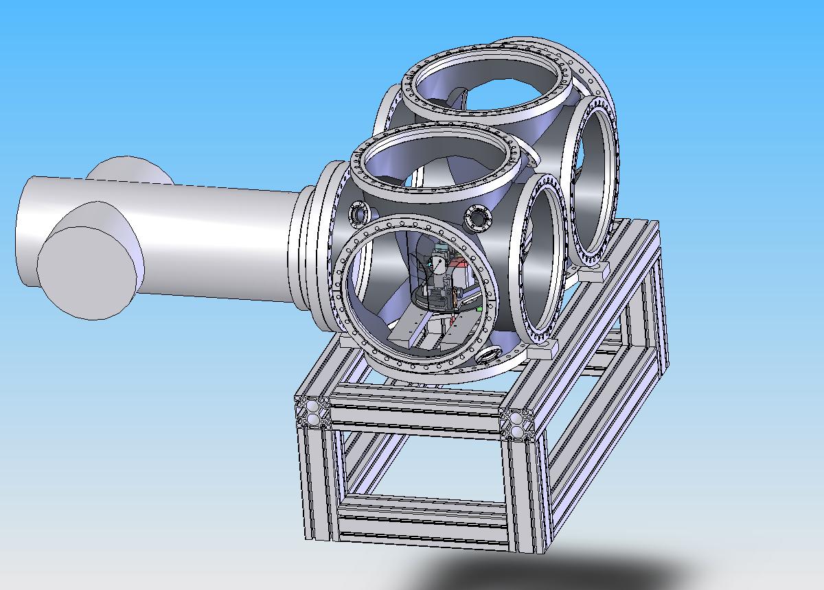
the minitec company has advised me to use the 90x90 S profiles. n.b. the correct way to mount the minitec posts. material stress will be 7N/mm2 and displacement 200um.
a better way to mount the chamber onto the frame is seen here, with steel taps on the bottom 360 flanges.
the viewports pointing downwards will be useless now. something for next week to think about.
the motor positioning thk company representative will come visiting next week.
weight and momenta of chamber etc.

for dimensioning the minitec frame, we need to know the forces etc.
(mm)
frame:
height 1290 (1600- 310(fel beam height-(chamber radius+space for chamber holder))
inner length 950 (chamber 1000 - 50 for chamber holder to be on frame)
inner broadness 420 (for 360 flange (with outer diameter 412mm) to fit through frame)
(kg)
chamber 27 kg
turbomolecular pump 60x3
360 blind flanges 30x10
<600kg
berlin cluster source 100 kg
700mm from main axis of chamber (500mm length + 200 chamber radius).
since we want to position the chamber in xyz, we need four frames, the chamber positioned on the inner, and the outer on solid ground.
the minitec company is performing stress analysis, to determine the profile (possibly either 45x90 or 90x90mm)
-for obtaining the freedom to rotate the chamber, we can ask a company to build a frame on struts, which would be positioned by hand.
-an alternative to fix the chamber onto the minitec frame is to solder steel ears onto the two bottom 360 flanges, which then are bolted onto the frame.
2006-05-11
berlin cluster source adds momentum

A major concern for the support of the chamber is the berlin cluster source of approx. 100kg, 500mm from the chamber flange.
2006-05-10
possible companies
the chamber can be made by scienta, an uppsala company:
vg scienta
the frame onto which the chamber will be mounted will possibly be:
minitec
the positioning of the chamber with um precision could be delivered by thk, i will meet a representative on friday:
thk
a possible breadboard to be mounted in the chamber and other optics equipment can be delivered by
thorlabs
they believe (but cannot guarantee) that the optics parts are vacuum compartible down to at least 10-6mbar. a breadboard mb1530/m (use the search option) fits nicely through a 360 flange, and on the rail support. if we need a longer breadboard, we can have two in series on the rail support.
of course nothing is decided yet about where to buy any equipment. i am just exploring the market.
2006-05-09
chamber on minitec frame w llnl experiment

the llnl experiment, as it was for the february beamtime, is positioned around iar 200. and the chamber is set onto a minitec frame.
stress analysis on the chamber
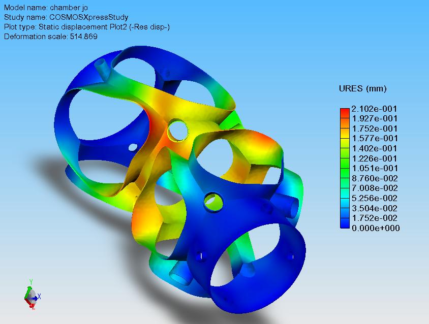
fos is 5.2. max deformation is 210 um. these figures will be much better with the flanges mounted.
2006-05-08
2006-05-07
chamber with viewports

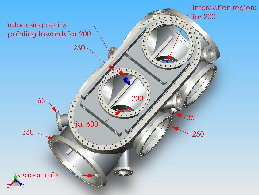
now i have the interaction regions (iar) at 200 and 650mm from the beamline flange. i have positioned the up, down and side 360 flanges, so that the 250 flanges can be centred around the iar's with off-centre 360-250 adapters. i have the positioned the viewports to look on either one of the iar's, or the submicron optics (red and blue pucks).
reason for keeping distance short
here is the reason for keeping the distance beamline flange-iar200 as short as possible. the submicron optics (blue puck) will redirect the beam in an angle, and if we want beam characterization mounted on the beamline flange, we need the short distance.


2006-05-05
minimizing flat surfaces

a key issue about vacuum chambers is to use self stable components. a round component is self stable (the pressure load is symmetric), a flat component, e.g. the sides of the top or the top itself, is not self stable. here, using two 360 cf flanges on top instead of the previous top part, we have almost as much access to the experiment as with the top part. and a more self stable geometry of the chamber. another option would be to stick to the previous top part, but make it elliptic seen from the top, and round with respect to the main axis of the chamber. this would be a complicated expensive option. viton o-rings for sealing the top part holds down to 10-8 mbar, good enough for our experiments (i.e. berlin clusters) and imaging of nanoparticles and fib structures.
2006-05-04


2006-05-03
top part v.2
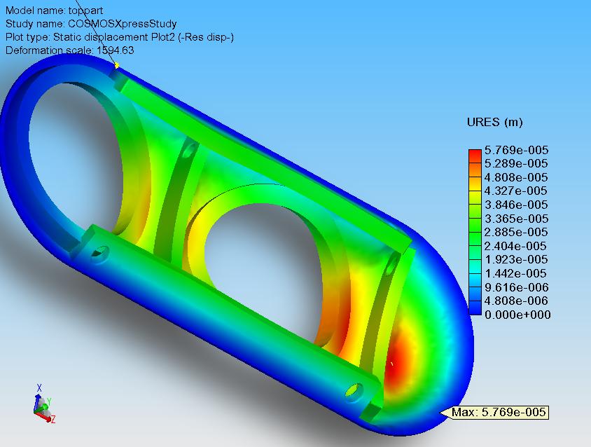
here is a more realistic simulation, compared to a week ago, of the stress on the top part of the chamber. factor of safety is 3.7 (>3 is ok).
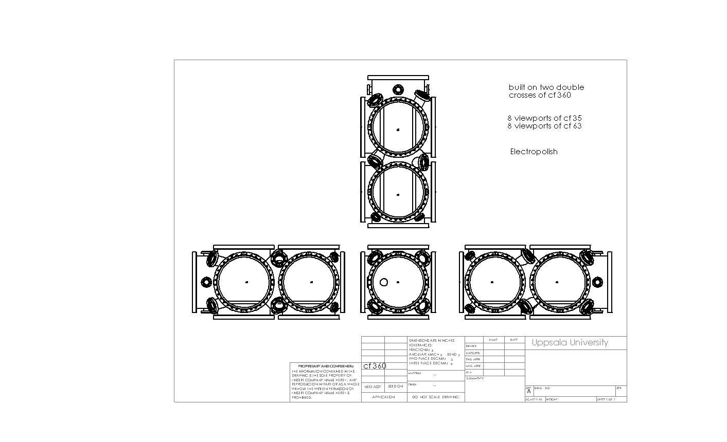
chamber with viewports
now viewports (vp) have been added to the chamber. the vps all point towards the interaction regions (iar) 200 or 600. n.b. by clicking on the figure, you get a larger view on the sheet.

2006-05-01
final word on top flange married to zeppelin chamber

here the impossibility of the top flange setup, used in hamburg last beamtime, implemented onto the zeppelin chamber. even when the experiment is centred, the interaction region will be above the top end of the 16inch front flange. however, the option to put the experiment onto the support rails remains an option.
2006-04-28
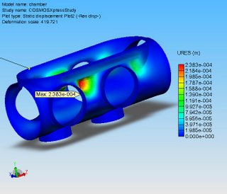
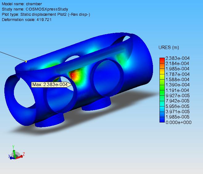
stress analysis with weird dimensions no. 2
the wall thickness of the chamber is 3mm. the factor of safety (FOS) is 3.5. (>2 is ok.) max. displacement is 238um.
stress analysis with weird dimensions

here is what happens to the top if we put 1atm (i.e. pumped chamber) onto the top. max. displacement is 34um. i have stabilized it with supports, which also can be used for removing the top (note the holes in the supports).
n.b.: you get a larger picture when you click on it.
2006-04-27
refocusing optics in chamber
i got a question from livermore, if refocusing optics would fit into the zeppelin chamber. in the upper left corner, my problem can be seen.
130mm is the distance for the livermore experiment top flange-interaction region.
100mm is the distance interaction region-beamline port.
the beamline port (1inch: 35mm) is as far out as possible on the 16inch: 360mm chamber flange. nevertheless i lack about 10mm for the beamline port to reach up to the interaction region.
the question is if we could rebuild the livermore experiment, so that we can support it from the support rails instead. then we have no problem fitting both the refocusing optics and the livermore experiment into the chamber.

2006-04-11
change of name x2
1) the free electron laser in hamburg was renamed on the 6th of april to FLASH (Free electron LASer in Hamburg). a great, funny name.
2) the uppsalachamber (see post below) is hereby baptized to Steel Zeppelin.
2) the uppsalachamber (see post below) is hereby baptized to Steel Zeppelin.
2006-04-06
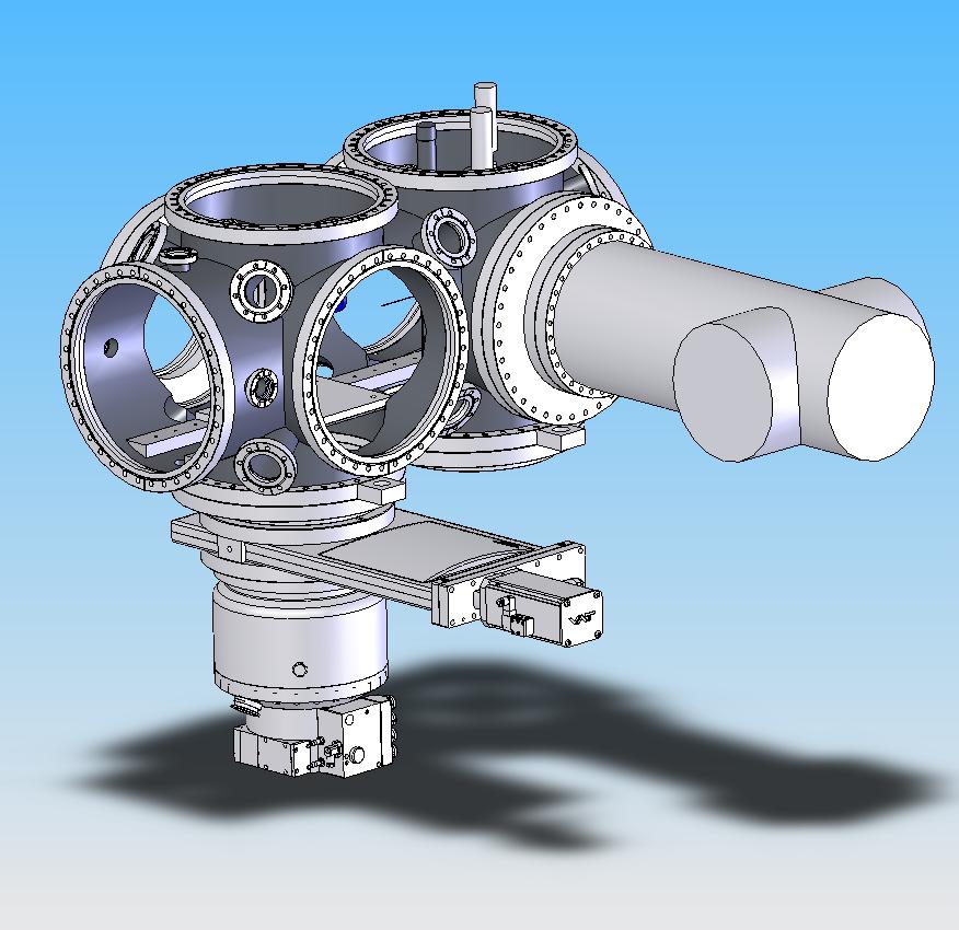
my first solidworks baby
max. symmetry:
two sets of four flanges (1x200; 3x 250): experiment can be set 200, 400 600 or 800mm from beamline flange.
the to allows either
1) max. accessibility: remove the elongated top or
2) standard flange access.
two supports along the chamber allow for flexible mounting of experiments.
two sets of four flanges (1x200; 3x 250): experiment can be set 200, 400 600 or 800mm from beamline flange.
the to allows either
1) max. accessibility: remove the elongated top or
2) standard flange access.
two supports along the chamber allow for flexible mounting of experiments.

2006-02-22
off-axis experiment
Antons comment:
"If we insert the LLNL imaging can in the system, could the experiment run with the beam off-centre? This could be done by swapping in a new front flange with an offset (slightly higher) beam entry port and lowering the whole chamber. Of course, we would need enough travel in the chamber support system to accomodate this (not a bad idea in the first place, to be able to place the FEL beam anywhere in the chamber). Plus it would be a good idea to have pitch and yaw control over the chamber itself (perhaps manual by turning screws, perhaps a 6-strut system?)"
the off-axis is a good idea, why did i not think of that option?
i have had a first contact with minitec in sweden today. unfortunately, they cannot provide us a micron positioning system. so we have to find something else.
2006-02-21
and the winner is... solidworks
we need to have full cad compartibility, either with llnl or tub, so we have decided to go for solidworks. it will be running in a few days.
2006-02-20
future of the blog

i leave hamburg for uppsala tomorrow. anyhow, i will continue this blog, now mainly with focus on the chamber. you are always welcome to email me, but if you feel that the info suits for the blog, you can comment on any given post. i would like this blog to be a forum for uppsala, llnl, berlin, hamburg,... i expect instant feedback if i should fail in judgement for what should be on the internet or not. when i post info of major interest, i will always send a notice email to the ones concerned. the blog has the main advantage that i do not have to send big attachments to a lot of people.
input from moellers
requests for the chamber, based on the alfa.2 version:
1) the top flange: preferably 250 (as the top flange now), or 200
2) main side flange: preferably 250 (as now), or 200
3) top, bottom and side flanges lined up
-the chamber base will be minitec based. minitec also provides servo motors for positioning. minitec is modular, so the cluster source can be mounted on minitec in berlin, and then mounted on the base in hamburg.
-if we make the two sets of: top, two side, and bottom flanges equal, and put the distance from the beamline side to the centre of the first set of flanges to 200mm, the centre distance between the two sets of flanges to 400mm, and the second set of flanges to 400mm from the rear side flange, i.e. from the side:
| 200 O 400 O 400 |
then we have the option to set the experiment 200, 400 (swap beamline and rear sides), 600 (200+400) or 800 (swap again, 400+400) mm from the beamline flange. that provides space for e.g. a delay device, apertures, or refocusing optics.
-a generous amount of 40, 60, ... viewports and feedthrough flanges on different geometries.
tp (experimentalist edition) knowledge: up to 200 (8 inch) there is one worldwide standard, 250 (10inch) and upwards have different standards.
2006-02-19
moeller lunch at 1am

katja eremina, christoph bostedt, heiko thomas, thomas moeller, hubertus wabnitz, tim laarmann and matthias hoener.
2006-02-17
cad program for macintosh?!
i would like _very much_ to work on my mac laptop. neither solidedge (hasylab, moller group) or solidworks (livermore) have mac versions.
i did find a 3D modeling program, for both mac and pc by googling:
amapi
matthias hoener from the moller group thinks it looks good on the homepage. it is compartible with solidedge and solidworks. they would be willing to switch program (from solidedge) to be compartible with us.
i did find a 3D modeling program, for both mac and pc by googling:
amapi
matthias hoener from the moller group thinks it looks good on the homepage. it is compartible with solidedge and solidworks. they would be willing to switch program (from solidedge) to be compartible with us.
experiment in uppsalachamber

the present experiment would be too high in the uppsala chamber. options:
-mount it on a base on the two support tracks.
-extend the holder of the experiment.
-a special-designed top square flange with a lowered flange hole.
alfa.2: matthias hoeners version

matthias hoener, a phd student in möllers group, made this draft.
-it is a tube (not square) chamber: better for pumping, cheaper, stands the 1atm vs. high vacuum force better.
-it has the advantages of the square chamber:
1) square removable top providing good access.
2) with the two supports with (not included in the drawing) windings, experiments on a base can easily be mounted.
-viewports can be mounted on reduction flanges on the front and back.
2006-02-14
uppsalachamber, cont.
i will go for hamburg tomorrow wednesday. the möllers still have beamtime, and they are part of the uppsalachamber project. let's see what they think of our proposal, see link below. i will learn how to use solidedge, a cad-program.
uppsalachamber: first draft
marvin seibert found a chamber on ebay:
ebay chamber
quote marvin: Hej Florian, there is a complete vacuum chamber up for sale on ebay. Looks like a diving bell and comes complete with pumps. Just for fun...
uppsalachamber: first draft
marvin seibert found a chamber on ebay:
ebay chamber
quote marvin: Hej Florian, there is a complete vacuum chamber up for sale on ebay. Looks like a diving bell and comes complete with pumps. Just for fun...
2006-02-08
last post for this beamtime
i am about to leave for uppsala. i will miss the pumpnprobe the next two days, i guess we will hear all about that anyway. to conclude, we were very lucky with the beam these weeks, apparently, the vuv-fel has never been running so well. quote henry chapman: "As for our experiment, we slam dunked it, we kicked the ball up the field against the wind, we hit a hole in one, we put the pedal to the metal, and we scored a six, a home run, and hung ten on the pipe."
end of confusion
for the last three shifts starting 7am today, ending 7pm on friday, we originally intended to perform pump&probe experiments, with a multilayer mirror mounted on the rear side of the latex balls.
our original plan was to use a 2nd harmonic: 16nm mirror, but our experience with 2nd harmonic measurements was not convincing. so we decided to use the fundamental wavelength, but the required mirror was in livermore. but fedex lost it: no-we-have-not-lost-it-we-just-do-not-know-where-it-is. so we had to give up on doing pump&probe today, instead we do regular scattering experiments on focussed ion beam (fib) structures and latex balls. urs, a swiss postdoc at livermore, is on a plane to germany, to deliver spare 32nm mirrors. he will arrive tonight in hamburg. so we will at least have two shifts of pumpnprobe experiments.
marvin from uppsala volunteered to get on the first flight this morning to get to san fransisco. he celebrated with champagne when urs could do it instead.
2006-02-06
uppsalachamber alfa.1: first draft

the dark-shadowed flange ports are 300mm (12 inch) large.
antons wishlist:
-2xDiagonal (45 deg) VP for looking at alignment HeNe on sample
-Good light-tight shutters for keeping dark signal low on CCD
-Space for 90 degree mirror arrangement (LLNL imaging mode)
-Plenty of pumping for particle injection experiments
-Front end could have focussing optic, or
-Differential pumping stage on front end to allow chamber to run at higher pressure?
24h shift: 30 degrees measurement

we will use this 24h shift (ending monday at 7pm) for the 30 degrees camera&mirror setting, so we can see the elastic scattering minimum around <30 degrees, see mie scattering simulations.
time for carrot juice!

janos hajdu, marvin "chocolate" seibert, henry chapman, mike bogan, calle caleman, magnus bergh and goesta huldt.
2006-02-05


network
göstas comments:
We now have a private wireless network through which we should be able to reach our data. Ask Gösta for the details of connecting.
One _should_ be able to see shared folders in our data computer
by enabling Windows Sharing on the Mac (System
Preferences -Sharing) and then using Finder-Go-Connect to server). After
some hassle, we got this to work for Florian. If you don't know the server address, ask someone.
You can ssh and such to our data computers local address. I still can't make recursive scp or rsync work (think sftp works). On the other hand, now that we are on the same network you can
log on to the data computer and rsync back to your computer. In that direction it
works, for me at least.
The wireless printer is connected to our private network, you can't use it from the public network anymore. Printing with the USB cable hasn't changed.
mounting of filter sample
titanium filter mounts for filtering out the fundamental 32nm, now we want 2nd harmonic (16nm) signal. credit to robert johnson.
2006-02-04
16nm mirror mounted
we mounted the 16nm mirror this morning. tonight we will start with HeNe laser alignment.
michail yurkov visiting the experiment


michail yurkov, the main man for the vuv-fel machine, was visiting our experiment this morning. the said that they do not understand the 2nd harmonic (16nm) radiation, it should not be there. and it can not be controlled or optimized. in contrast, the 3rd harmonic at 11nm is well understood. in the future, we should therefore aim for the 3rd harmonic.
later today, i got a 10 minute lecture of evgeny l. saldin, who invented self-amplified spontaneous emission, sase, at the age of 23 in the early eighties. i am generous enough to share my new expertise.
connecting to mie computer
Göstas comments:
We know have a Desy account that should let us log in to any Windows or Unix
computer here. Ask around for the username and password.
There is also an ssh/scp/sftp server on the data computer. Unfortunately you
cannot connect directly to the data computer unless you are hooked up to the
internal network. Here is a work around:
1)
Add the following line to your /etc/hosts file
(C:\WINDOWS\system32\drivers\etc\hosts on WinXP):
127.0.0.1 mie
2)
Open an ssh tunnel to bastion.desy.de:
ssh -l vuvupp -L 22:hasbl2mie.desy.de:22 bastion.desy.de
3)
As long as this tunnel is alive, you should be able to connect to our data
computer with ssh/scp/stp, using the alias mie for the host name. For
example, ssh username@mie. Ask around for the username and password.
2006-02-03
visits
yesterday, sebastiens wife was around. and so was marvin seibert, a phd student from our group in uppsala. he did not disappoint us, and brought a bag full of choclate.
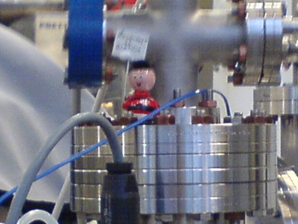
and the beamline from now on has its own saint. let me introduce zé, the flamengista.
the people here now are: sebastien, mike, stefano, henry and anton from llnl, janos, magnus, gösta, calle, ricardo and me from uppsala.

2006-02-01
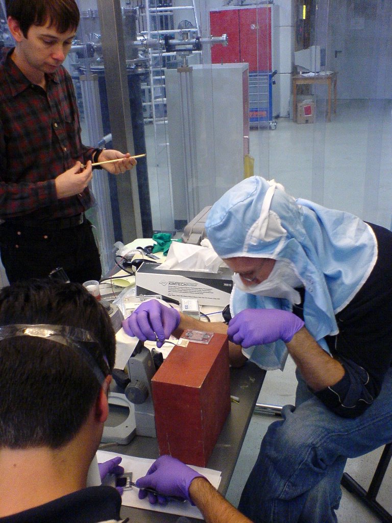
experiment into chamber
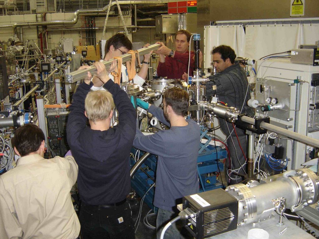
these photos were taken on sunday, as our experiment was mounted into the möller chamber.
fast shutter
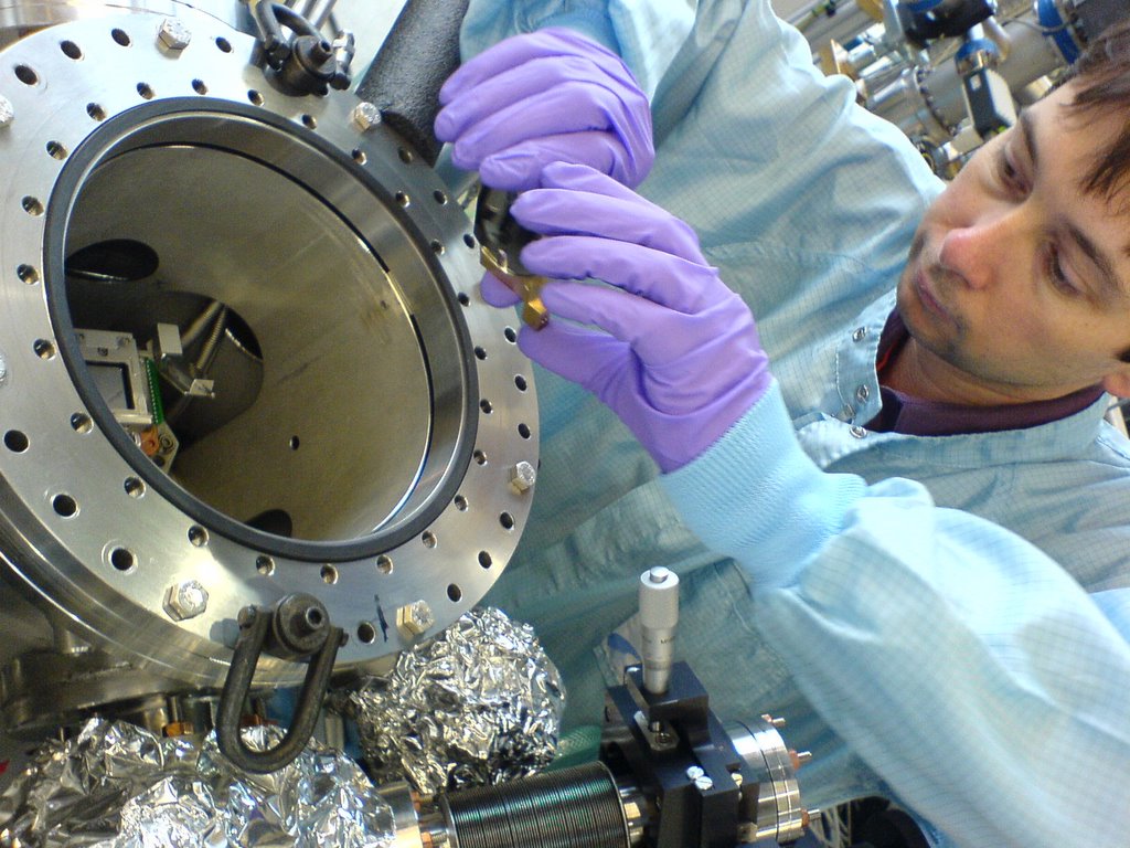
the fast shutter has a shutter lifetime of 10000 shots (VERY limited, not sufficient for even a single beamtime, and we are a few user groups who need it). the vuv-fel crew are working on a shutter with a longer lifetime.
the shutter is seen in the photo. on the top of the chamber, a dc motor controls a shutter made of graphite, which is mounted through the dark bellow on the top flange.
there are three commmands for the shutter, operated from the vuv-fel software doocs: closed, open and click, i.e. it opens for a single shot. for this beamtime we will work with a manual control of the fast shutter. the staff is afraid of the possibility that our labview program will make it too easy for us to shoot of the 10000 precious events.
now anton has programmed it so that if we want to take a ccd image
1) for a single shot:
a) close shutter in doocs
b) start exposure in labview
c) click shutter in doocs
d) exposure will close automatically (exposure time predefined in labview)
2) over many shots:
a) start exposure in labview
b) open shutter in doocs
c) exposure will close automatically (exposure time predefined in labview)
bicycle at the vuv-fel
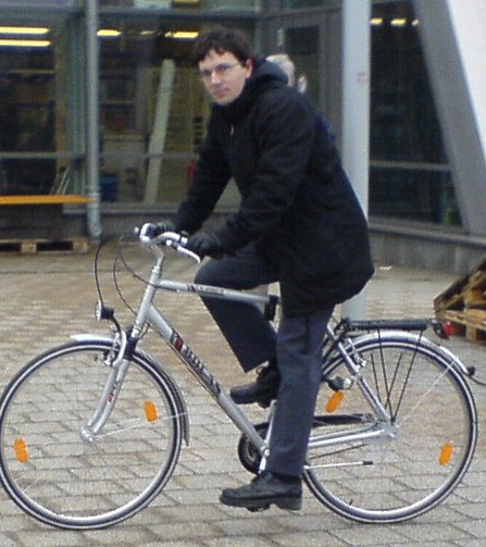
i have bought a bike of brand bocas which everybody can use here in hamburg. if you want to use it when we are not here, ask thomas tschentscher.
Subscribe to:
Posts (Atom)