a few parameters to be considered for pumping:
1x10^-8 mbar vacuum.
the load of the rare gas clusters is 0.1mbar x l/s, requiring a 1000l/s turbomolecular pump.
the inner area of the chamber is 2m^2.
the volume of the chamber is 0.16m^3.
the area of the llnl experiment is 3m^2.
for the previous experiment we had a 1000l/s pfeiffer corrosiveturbo vacuum pump, which needs a backing pressure of 10^-2 mbar. a scroll pump is good for that.
comments from christoph bostedt, berlin:
S=R*A/p
and R=8*10exp-9 mbar/(sec*cm^2) (outgassing stainless steel after one hour pumping), A ca 2*10exp4 cm^2, p=10exp-8mbar
i.e. 16000 l/sec needed sucking capability. which would be gigantic!
to save the day: R can be reduced by electropolishing, and we can work at worse vacuum than 1e-8mbar, so we can reduce S by an order of magnitude.
so we would need app. 2 1000l/s pumps for the chamber, and 1 1000l/s pump for the clusters.
2006-05-24
2006-05-23
positioning of the chamber
thk: csr
yesterday, thk representatives were here to present their product. now i am waiting for them to present a full 6dof (six degrees of freedom: xyz, and three angles) positioning solution, possibly based on the csr standard. the motors for the positioning of the linear motion (lm) blocks would be provided by omron.
the previously used positioning setup of the moller group was also based on thk, with
phytron motors. phytron is the standard at desy.
the previous thk:csr setup was normal precision grade, i.e. stable and repeatable position on a 10um scale. thk also provides super precision and ultra precision grade, with 7 and 5um precision, respectively.
with the submicron optics, we need submicron stability over 10 minutes (a low-fluence run). over 12 hours, we need 10um stability.

2006-05-12
chamber on minitec frame
the minitec company has advised me to use the 90x90 S profiles. n.b. the correct way to mount the minitec posts. material stress will be 7N/mm2 and displacement 200um.
a better way to mount the chamber onto the frame is seen here, with steel taps on the bottom 360 flanges.
the viewports pointing downwards will be useless now. something for next week to think about.
the motor positioning thk company representative will come visiting next week.
weight and momenta of chamber etc.

for dimensioning the minitec frame, we need to know the forces etc.
(mm)
frame:
height 1290 (1600- 310(fel beam height-(chamber radius+space for chamber holder))
inner length 950 (chamber 1000 - 50 for chamber holder to be on frame)
inner broadness 420 (for 360 flange (with outer diameter 412mm) to fit through frame)
(kg)
chamber 27 kg
turbomolecular pump 60x3
360 blind flanges 30x10
<600kg
berlin cluster source 100 kg
700mm from main axis of chamber (500mm length + 200 chamber radius).
since we want to position the chamber in xyz, we need four frames, the chamber positioned on the inner, and the outer on solid ground.
the minitec company is performing stress analysis, to determine the profile (possibly either 45x90 or 90x90mm)
-for obtaining the freedom to rotate the chamber, we can ask a company to build a frame on struts, which would be positioned by hand.
-an alternative to fix the chamber onto the minitec frame is to solder steel ears onto the two bottom 360 flanges, which then are bolted onto the frame.
2006-05-11
berlin cluster source adds momentum

A major concern for the support of the chamber is the berlin cluster source of approx. 100kg, 500mm from the chamber flange.
2006-05-10
possible companies
the chamber can be made by scienta, an uppsala company:
vg scienta
the frame onto which the chamber will be mounted will possibly be:
minitec
the positioning of the chamber with um precision could be delivered by thk, i will meet a representative on friday:
thk
a possible breadboard to be mounted in the chamber and other optics equipment can be delivered by
thorlabs
they believe (but cannot guarantee) that the optics parts are vacuum compartible down to at least 10-6mbar. a breadboard mb1530/m (use the search option) fits nicely through a 360 flange, and on the rail support. if we need a longer breadboard, we can have two in series on the rail support.
of course nothing is decided yet about where to buy any equipment. i am just exploring the market.
2006-05-09
chamber on minitec frame w llnl experiment

the llnl experiment, as it was for the february beamtime, is positioned around iar 200. and the chamber is set onto a minitec frame.
stress analysis on the chamber
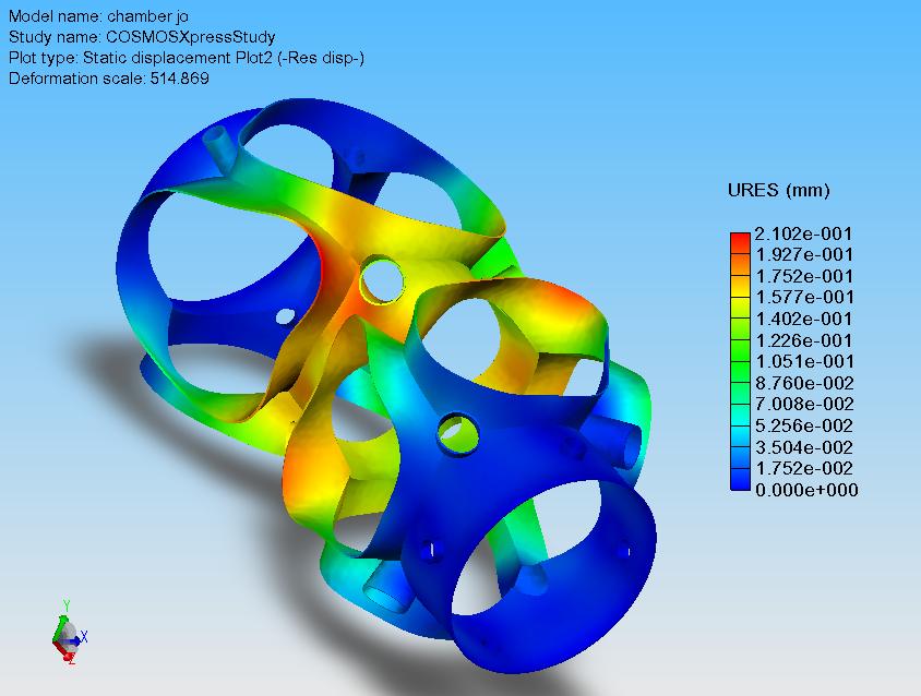
fos is 5.2. max deformation is 210 um. these figures will be much better with the flanges mounted.
2006-05-08
2006-05-07
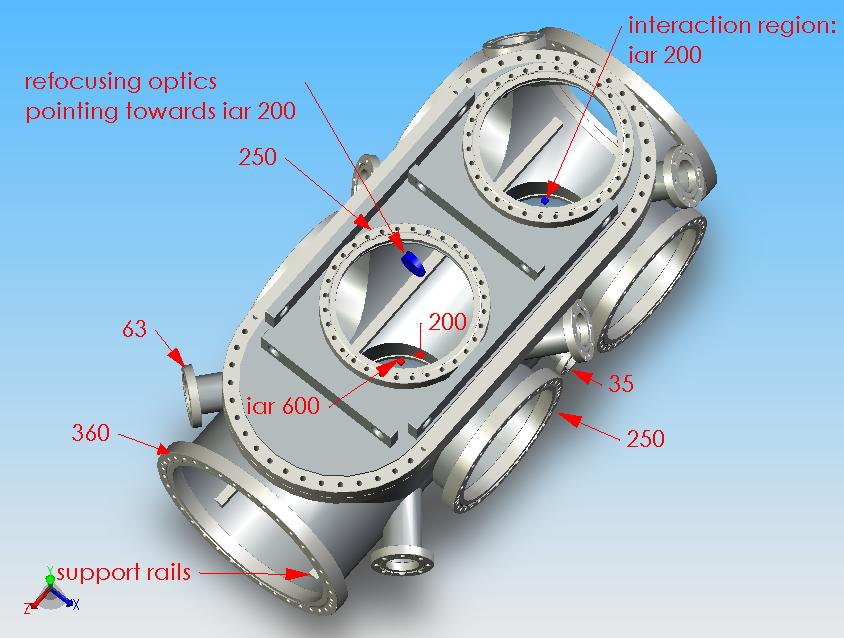
chamber with viewports

now i have the interaction regions (iar) at 200 and 650mm from the beamline flange. i have positioned the up, down and side 360 flanges, so that the 250 flanges can be centred around the iar's with off-centre 360-250 adapters. i have the positioned the viewports to look on either one of the iar's, or the submicron optics (red and blue pucks).
reason for keeping distance short
here is the reason for keeping the distance beamline flange-iar200 as short as possible. the submicron optics (blue puck) will redirect the beam in an angle, and if we want beam characterization mounted on the beamline flange, we need the short distance.


2006-05-05
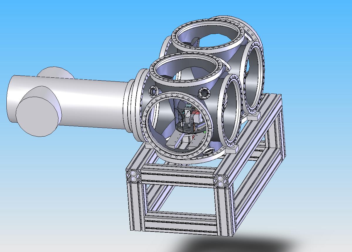
minimizing flat surfaces

a key issue about vacuum chambers is to use self stable components. a round component is self stable (the pressure load is symmetric), a flat component, e.g. the sides of the top or the top itself, is not self stable. here, using two 360 cf flanges on top instead of the previous top part, we have almost as much access to the experiment as with the top part. and a more self stable geometry of the chamber. another option would be to stick to the previous top part, but make it elliptic seen from the top, and round with respect to the main axis of the chamber. this would be a complicated expensive option. viton o-rings for sealing the top part holds down to 10-8 mbar, good enough for our experiments (i.e. berlin clusters) and imaging of nanoparticles and fib structures.
2006-05-04


2006-05-03
top part v.2
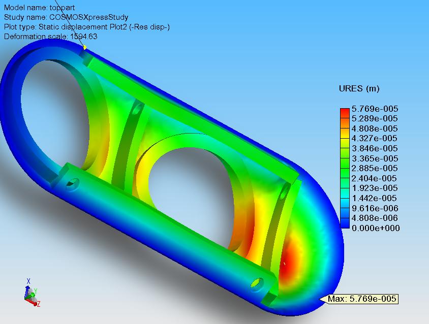
here is a more realistic simulation, compared to a week ago, of the stress on the top part of the chamber. factor of safety is 3.7 (>3 is ok).
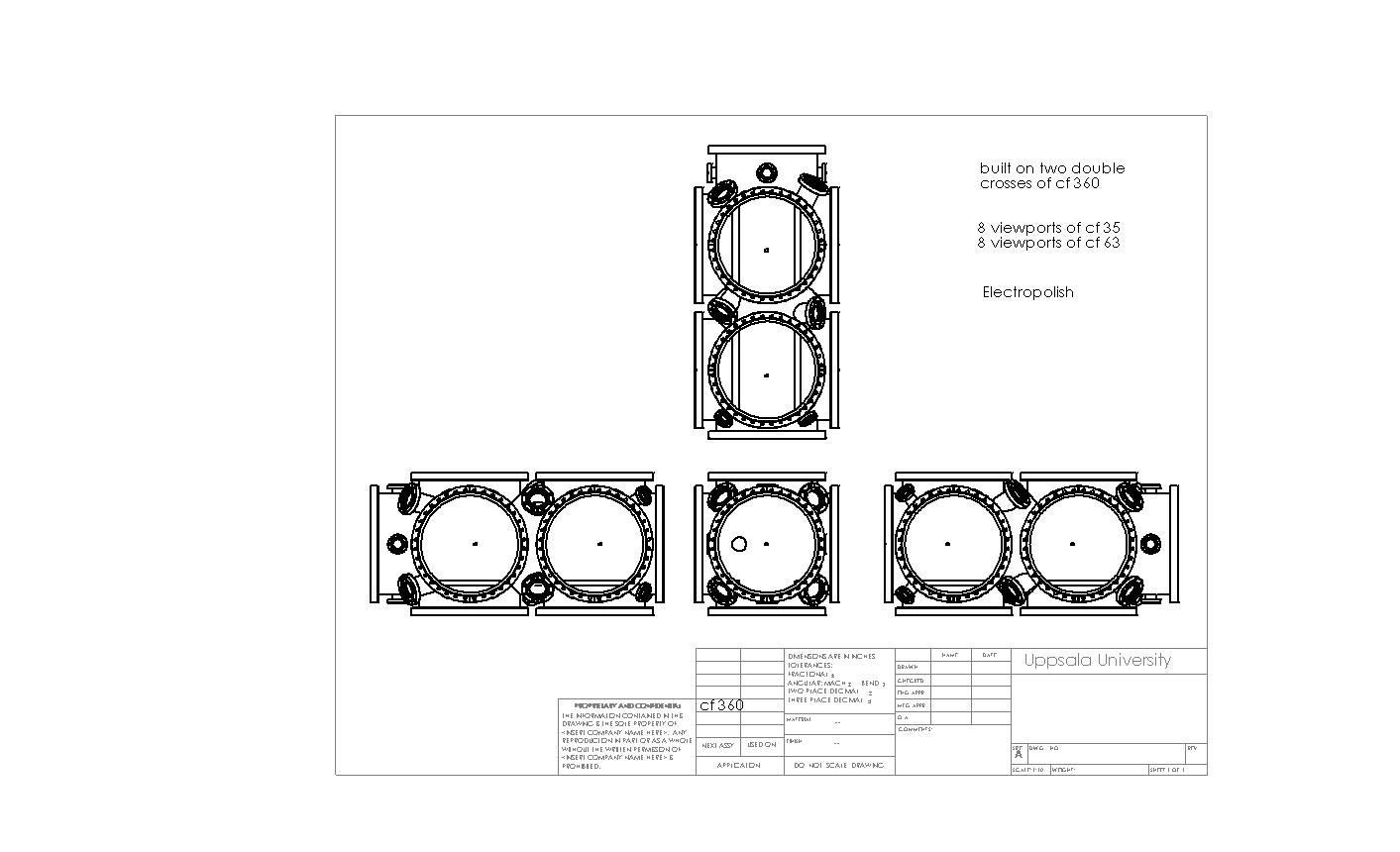
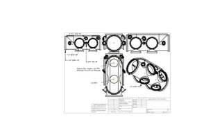
chamber with viewports
now viewports (vp) have been added to the chamber. the vps all point towards the interaction regions (iar) 200 or 600. n.b. by clicking on the figure, you get a larger view on the sheet.

2006-05-01
final word on top flange married to zeppelin chamber

here the impossibility of the top flange setup, used in hamburg last beamtime, implemented onto the zeppelin chamber. even when the experiment is centred, the interaction region will be above the top end of the 16inch front flange. however, the option to put the experiment onto the support rails remains an option.
Subscribe to:
Posts (Atom)