2006-10-05

Discussion for Thursday the 9th with Allectra


I will go to Parma tomorrow (Wednesday) to see the chamber, and meet with Mario Peli, the Allectra engineer. And eat some prosciutto. :)

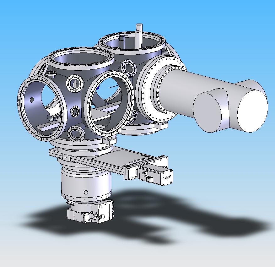
We intend to use the chamber in November for test purposes. The particle injection system will be mounted from the left, a Nd:YAG laser comes from the front and a beam dump/ power meter will be mounted on the rear side.

Before, we discussed the option to have off-centre CF 360-35 nipple adapters.
The IAR, Interaction Region, is given by the distance to the 250 top flange (presently given by the Berlin chamber).

However, it is much more convenient to have the interaction region at the centre. That would require a CF 360-250 well adapter, with a depth of 156mm. The problem to solve is that there is space for nitrogen pipes (Swagelok connections on the top 250 flange, pointing to the right). The special geometry of this well adapter is the first topic to discuss in Parma.

List of topics:
1) Well adapter (see above).
2) Geometry of the viewports, so that they do not collide with the 360 flanges.
3) 360-35 nipple adapters.
4) Support for the breadboard in the chamber (previously misleadingly denoted rails).
5) Date for chamber delivery to Flash.
6) Lugs, the interface chamber-stand.

2006-07-11

Drawings sent to Allectra


Here is the drawing file of the Zeppelin chamber that I have sent to Allectra. Production time is 10 weeks, so we can expect to have the chamber delivered at the end of September.

On the drawing at least 1 source of potential confusion can be seen:

1) According to Henry Chapman, the submicron optics will be placed 100mm off-axis, 250mm downstream the chamber. So the submicron plane would be 220+250=470mm from the front flange. I have instead put it slightly off: at 445mm. It is a compromise, with a submicron plane at 400, we could use the submicron optics pointing towards the interaction region IAR670. Now the viewports can be used for both possible geometries.

In an earlier version of this blogpost, a second potential source of confusion was mentioned, but since then the interaction regions IARs were set to be centered with the CF360 flanges, simply to minimize confusion.

The definite geometry of the rails will be postponed until I have interacted more with the people constructing the parts to mount there.

I can send you eDrawings, DXF, DWG, etc. files on the chamber if you want to have a closer look. Last minute changes are welcome until Thursday the 13 of July.

2006-06-08

Movie

I have started with videoclip recording on the chamber. Anyone interested? Can be used for ppt presentations etc. Formats: avi, bmp or tga. (OK for e.g. Quicktime, Windows Media Player, etc.).

Pumping, cont.


Why not using a cryopump, e.g.: shi?

The initial costs are comparable to a turbopump, the maintainance costs are significantly lower.

The main reason why cryopumps are not standard for experiment chambers is that they vibrate (remember the 2Hz tf-tf-tf from the mono beamline at the Flash). I will get specs on the vibrations.

Back to turbos, an issue is to prevent the rotating alu blades from, e.g. falling screws.
-The standard solution is a net. The drawback is 25% reduced pumping efficiency.
-If we choose to mount the turbo to the side or upwards, we will not need any net. But the chamber will be less bottom-heavy.

2006-05-24

pumping

a few parameters to be considered for pumping:
1x10^-8 mbar vacuum.
the load of the rare gas clusters is 0.1mbar x l/s, requiring a 1000l/s turbomolecular pump.
the inner area of the chamber is 2m^2.
the volume of the chamber is 0.16m^3.
the area of the llnl experiment is 3m^2.

for the previous experiment we had a 1000l/s pfeiffer corrosiveturbo vacuum pump, which needs a backing pressure of 10^-2 mbar. a scroll pump is good for that.

comments from christoph bostedt, berlin:

S=R*A/p

and R=8*10exp-9 mbar/(sec*cm^2) (outgassing stainless steel after one hour pumping), A ca 2*10exp4 cm^2, p=10exp-8mbar

i.e. 16000 l/sec needed sucking capability. which would be gigantic!

to save the day: R can be reduced by electropolishing, and we can work at worse vacuum than 1e-8mbar, so we can reduce S by an order of magnitude.

so we would need app. 2 1000l/s pumps for the chamber, and 1 1000l/s pump for the clusters.

2006-05-23

positioning of the chamber

thk: csr
yesterday, thk representatives were here to present their product. now i am waiting for them to present a full 6dof (six degrees of freedom: xyz, and three angles) positioning solution, possibly based on the csr standard. the motors for the positioning of the linear motion (lm) blocks would be provided by omron.
the previously used positioning setup of the moller group was also based on thk, with
phytron motors. phytron is the standard at desy.
the previous thk:csr setup was normal precision grade, i.e. stable and repeatable position on a 10um scale. thk also provides super precision and ultra precision grade, with 7 and 5um precision, respectively.
with the submicron optics, we need submicron stability over 10 minutes (a low-fluence run). over 12 hours, we need 10um stability.

dr emma


on friday, my emma got her phd! hurrahurrahurrahurra!